Advanced simple compressor/limiter
The simple song:
It is organised as building blocks,
combined according to personal taste and need,
best if organised on a pre-drilled universal printed circuit board,
with holes for the input, output sockets, potentiometers,
all drilled into pcb,
then screwed and fixed with bolts,
with holes-conforming alu frontplate drilled in parallel,
and later pushed over it,
which would even act as Faraday cage,
besides being nice & shinny;
solution for the bottom?
-> I leave totally to your aesthetic touch,
but the mixer will be ‘elegantly’ slim,
because we’ll use an outside universal power plug.
This is what Monika wanted
.
.
.
.
.
.
.
.
.
.
.
.
.
.
LINE 1stereo in
.
.
.
.
prelisten / two pushbuttons
.
.
.
.
.
LINE 2 stereo in
.
prelisten/ two pushbuttons
.
.
.
.
.
ouputs
main mix L, R
(4x cinch)
.
send submix
(2 x cinch)
.
.
.
.
.
left
right
headphones amp
phones
6,3 mm socket
(two?)
And here is a ‘physical’ layout
consisting of:
-> one microphone preamp,
-> one (passive) stereo line input,
-> one channel output amplifier,
-> stabilizer circuit
… and its elements follow (with certain variations):
but before the nice drawings download there is time for a brief ‘basics’
course!
![]() The main elements
The main elements
used throughout are:
– resistor
– capacitor
– operational amplifier
The first two are ‘passive’ elements and op-amp is an ‘active’ element.
Also: the first two are ‘two-terminal’ elements and the op-amp is a ‘three-terminal’
element.
![]() Resistor has the ability
Resistor has the ability
to define the current that flows through it when a voltage is applied to
its terminals. Vice-versa: when a current flows through it a precise voltage
drop appears on its terminals. The simple (most frequently used) formula
is:
U = R x I (also: R = U / I
and I = U / R)
-> the first formula you read as: when a current of value I
flows through a resistor of value R it produces a voltage drop of
valuer U accross its two terminals. In audio mixer we use resistors
to adapt the internal resistences (-> impedances) of op-amps. Also: to
define the necessary voltages by ‘dropping’ them with resistor combinations.
![]() Capacitor (in our use)
Capacitor (in our use)
is an element that blocks the DC (direct current) voltages (-> supply voltages)
but lets through the AC (alternate current) voltages (-> signals). We need
DC voltage to supply the energy to the active element and to define its
optimum working conditions). Also: capacitors are used to store the energy
(-> we use it as such in stabiliser circuit) or to filter out the undesired
AC voltages (-> we use it as such in ‘decoupling’ the DC voltage supply
lines).
![]() We combine resistors in series
We combine resistors in series
or in parallel to achieve different values of resistence according to these
two formulas:
– for two resistors in series -> R1 + R2 = R3
– for two resistors in parallel -> 1/R1 + 1/R2 = 1/R3
![]() Also we can combine capacitors
Also we can combine capacitors
for the same reason:
– two capacitors in series -> 1/C1 + 1/ C2 = 1/C3
– two capacitors in parallel -> C1 + C2 = C3
try to imagine all these as water-pipe sistem which fills bath-tubs:
– generator takes care that the water pressure (-> voltage) in
the system is high enough for the water (-> current) to flow.
– pipes of different diameter allow more or less flux of water (->
resistence). Two pipes in parallel allow twice as water (-> current) to
pass.
– bath-tubs are filled with water according to their volume capacity
(-> capacitors). Two bath-tubs present double the water capacity.
– what about series of two pipes, bath-tubs? It’s not that easy to
imagine anymore.
![]() Impedance is a term defining
Impedance is a term defining
the ‘passive’ nature of elements (the one that ‘consumes’ the energy).
For audio frequencies we can assume that resistor has only resistence and
that capacitor has only capacitance. Active element also has both, but
because we use the most ‘perfect’ active element – operational amplifier,
we can forget impedances and simply say:
![]() Operational amplifier
Operational amplifier
is a three-terminal (input terminal, output terminal and common terminal)
active (ampifying) element with infinite input resistence, zero output
resistence and infinite amplification (->A). The basic formula is:
Uout = A x (Uin+ – Uin-)

![]() Depending of configuration
Depending of configuration
op-amp can be inverting or non-inverting (-> it inverts the
phase of input signal, or the output is ‘in phase’ with the input). For
such reasons it has two inputs: inverting (-) and non-inverting (+). Configuration
is defined by passive elements in the ‘feedback loop’.
![]() Feedback loop means
Feedback loop means
connecting output back to the input (-> taking part of the output signal
and bring it to one of the inputs). Two main configurations are:
-> non-inverting amplifier (pretending that op-amp is ‘perfect’)
Uout = Uin x (Rf + Rs)
/Rs
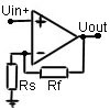
-> inverting amplifier (again: simplified!)
Uout = Uin x (1 + Rf/Rs)
where Rs is not only the resistor but also the inner resistence of
the source itself (-> microphone, whatever…)
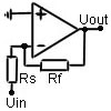
![]() We will use non-inverting
We will use non-inverting
amplifier for all stages because the input source does not define its amplification
(-> the source is ‘buffered’).
![]() Combining all three:
Combining all three: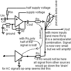
– first we define the optimum working conditions for op-amp:
the output is (‘biased’) at middle voltage point (‘potential’) between
positive supply voltage and negative supply voltage (-> here: ground).
This point we define at + input of op-amp by bringing the half supply
voltage to it (through Rin resistor). The – input must also be ‘biased’
to half voltage but this is performed automatically from teh output (through
Rf resistor) and by blocking the DC path through Rs with capacitor Cs (DC
current cannot pass through capacitor – therefore infinite resistence for
DC but short-circuit for AC signals).
– then we block all inputs and outputs of op-amp with capacitors, so
that DC voltages that only serve for internal op-amp biasing do not worry
us anymore. The only thing about value of DC blocking capacitors is that
it defines the lowest frequency point of signal. A formula:
f = 1/(2 x 3.14 x Rin xCin)
, must give around 10Hz
– when ‘mixing’ various inputs we must take care not to lose signals
from other sources because of the zero internal resistence of op-amps.
Therefore we put additional Ro resistors in series with op-amp outputs.
Each op-amp ‘sees’ his Ro and a parallel combination of all Ro’s from other
inputs. Study the above picture well – there is the basic principle.
and now the nice drawings must have downloaded!
![]() all input signal grounds
all input signal grounds
should go directly to stabilizer one-point ground, (however – they can
be first connected connected all together)
![]() the alu frontplate should
the alu frontplate should
be connected only once to ground -> at a microphone input (the most sensitive
one),
capacitor at the input should be 1microfarad plastic foil, resistor
100Kohm going from the input socket to ground is to prevent a ‘thump’ when
connecting an input cable;
![]() there is a possibility for
there is a possibility for
a ‘phantom’ microphone supply – the red resistor; attention: there are
electret microphones which have an additional ring -> like the stereo
mini jacks – these get their ‘phantom’ power at the ring (get a stereo
input socket!) – connect the red resistor on the ring;
![]() the trimmer may serve for
the trimmer may serve for
setting the input sensitivity but it can be also eliminated – together
with the associated 10 microfarad electrolitic capacitor.
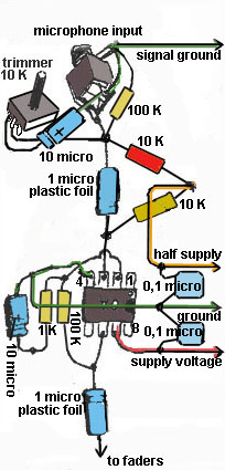
![]() Micro preamp is the simplest
Micro preamp is the simplest
operational amplifier non-inverting design, therefore a good op-amp is
needed (TL 071, NE 5534, CA 3140); the design is for single voltage supply
(and op-amps are not), therefore half_the_supply voltage line is needed
everywhere.
![]() also: very close to every
also: very close to every
op-amp a couple of ‘blocking’ capacitors (0,1microfarad 50V ceramic) are
needed (to block the noise from the two voltage supply lines).
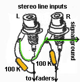
![]() For stereo (or mono) line
For stereo (or mono) line
inputs no op-amp is used, just resistor from the input socket to the ground
and capacitor from the input socket to the next (mixing, prelistening,
send) stage;
![]() however, adding a ‘buffer’
however, adding a ‘buffer’
stage (-> a mic preamp with feedback resistor replaced by a wire) can make
things easier with send potentiometers (-> cheaper and smaller!). Double
op-amps can be used (also 8 pins/ same price! -> NE 5532, TL 072,…).
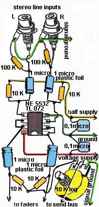
![]() this is how a buffer (with
this is how a buffer (with
double op-amp) looks like:
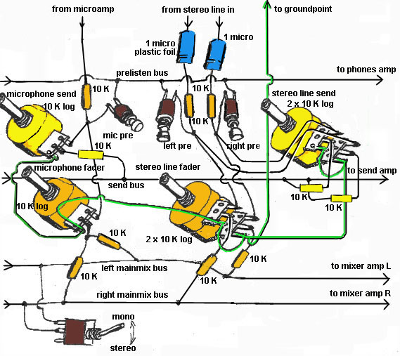
![]() The place for pre-fader (pfl)
The place for pre-fader (pfl)
send potentiometers is just before main mixer faders (one more SUM amp
is needed -> for mono send submix).
![]() The elements for send submix
The elements for send submix
are in yellow colour. If you don’t need send submix you can eliminate all
the yellow elements. If you need more submix groups just replicate same
‘ yellow’ configurations.
![]() Double potentiometers are
Double potentiometers are
necessary because we don’t use ‘buffers’ for the line inputs (-> look up ![]() ).
).
![]() Faders here are rotary logaritmic
Faders here are rotary logaritmic
potentiometers (instead of ‘sliders’ which are not cheap, or no good!),
however better (more expensive) pots will serve you better, double for
the stereo input control, single for the mono/ microphone control.
![]() After faders (through equal
After faders (through equal
value resistors) we connect (for the stereo inputs) all left to the left
sum common strip (bus), all right to the right sum common strip and for
the mono/ microphone to both (one resistor goes to left sum strip, one
resistor goes to right sum strip).
![]() Prelistening can be done
Prelistening can be done
easiest by pushbuttons, taking the signal from before the fader – simplest
solution uses just two-pole pushbutton (-> connected when pushed), more
practical solution needs a three-pole pushbutton (see the picture? soon!)
– one pole (the middle one in three-pole) goes to (common) prelisten line
(strip, bus) and further to the phones volume potentiometer.
![]() For the stereo/ mono switch
For the stereo/ mono switch
of mixer output use a two-pole switch between the left sum strip and the
right sum strip.
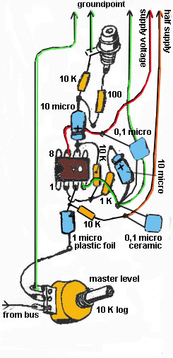
![]() At this point we can add
At this point we can add
another double potentiometer (same as the above ones) for the master level
-> and now we come to summing amplifiers:
![]() Summing amplifiers amplify
Summing amplifiers amplify
the sums of input signals and provide for the impedance transformation
(from high to low) – which serves best for feeding the output signal to
amplifier, headphones, computer,…
![]() We need two/ three kinds ->
We need two/ three kinds ->
for the prelisten/ phones, for the main mixer output, for the send submix
output (if needed).
![]() Again they are build in the
Again they are build in the
exactly the same manner as the microphone preamps – except the feedback
resistor (going from pin 6 to 2) is about 10 times smaller -> 10Kohms.
But for phones amplifier it should be larger -> 100Kohms. Experiment with
this (feedback) resistor!
![]() All connections to grounds
All connections to grounds
should go separately to common ground point in stabilizer (see above) and
all the voltage supply lines should also go separately to stabilizer (and
again: blocking capacitors should be used with each op-amp).
![]() The best would be to think
The best would be to think
of the ground connections which go to op-amps pins 4 as voltage supply
lines – complementary to the plus voltage supply line – these two leads
should be ‘twisted’ together to prevent any ‘hum’ induction.
![]() Grounds which go from the
Grounds which go from the
potentiometers are (same as input and output grounds) – ‘signal’ grounds.
Acting in this manner you prevent any possibility of ‘buzz’ or ‘hum’.
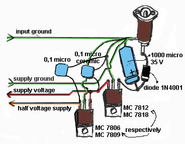
![]() Capacitors of 10 microfarads
Capacitors of 10 microfarads
are electrolitic (polarized! take care!) and they should be rated for voltages
above the supply voltage -> 25V will do. Largest electrolitic capacitor
is the 1000 microfarad in the voltage supply stabilizer part which should
have 35 V. Just for the case!
![]() And the minus pole of this
And the minus pole of this
capacitor should act as the common ground point for all the blocks!
![]() We get power from an outside
We get power from an outside
‘adapter’ of 12V to 24V DC secondary voltage (100mA is OK), which lets
us play safely because we don’t deal with lethal tensions anymore! Just
get the right socket, connect its + socket via a forward biased diode and
it will be impossible to ruin the mixer with different adapters.
![]() The stabilizer circuit is
The stabilizer circuit is
the most common MC 78xx (xx = 12 or 18, which is the stabilized output
voltage). To make use of the larger dynamic range (before clipping) of
output signal – find an adapter of 18-24V DC and use MC 7818 (and MC 7809
as you’ll find in the next paragraph).
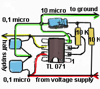
![]() The op-amps need a split
The op-amps need a split
voltage supply, so we let them float exactly in the middle of stabilized
supply voltage and ground. This is done by voltage divider resistors and
a voltage follower (again an op-amp!) or we could use another MC 78yy (yy
= half the xx) just after the first one. The second one is a better solution
in some ways but it does not adapt if for any reason a change in main stabilised
supply voltage occurs.
![]() And that’s all (for now).
And that’s all (for now).
In future you may expact some image files for PCBs, because the building
on the perforated board seems too much time & energy consuming.