FizziCalc
Intermediate
Advanced
Cool Topics
Reference
Search
Games and Fun Stuff
Meeting Forum
Physics Links
Induced Electromotive Force |
|
Return to the Advanced Level Page.
Electrical engineering's development began with Faraday and Henry who, independently, discovered the principles of magnetically induced electromotive force and methods for converting mechanical into electrical energy directly.
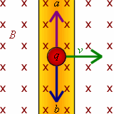 The illustration at right shows a wire of length l in a magnetic field B that is into the page (the x's stand for into the page; · stand for out of the page).
If you move the wire with a velocity v to the right, the magnetic field will interact with the charges q in the wire.
If you are thinking of positive charges, you would use your right hand, with your thumb pointing in the direction of the velocity and your four other fingers pointing into the page.
The force that the positive charges experience would be toward point a.
If you are thinking of negative charges, you would use your left hand, and the force that the charges experience would be toward point b.
The force that the charges experience is equal to F = qv × B.
The illustration at right shows a wire of length l in a magnetic field B that is into the page (the x's stand for into the page; · stand for out of the page).
If you move the wire with a velocity v to the right, the magnetic field will interact with the charges q in the wire.
If you are thinking of positive charges, you would use your right hand, with your thumb pointing in the direction of the velocity and your four other fingers pointing into the page.
The force that the positive charges experience would be toward point a.
If you are thinking of negative charges, you would use your left hand, and the force that the charges experience would be toward point b.
The force that the charges experience is equal to F = qv × B. Because you have moving charges, you create a change in potential difference.
This potential difference is said to be the induced electromotive force (EMF).
Now let's say we have a moving conductor on a stationary U-shaped conductor as illustrated at left.
When the moving conductor has a length of l and moves across the U-shaped conductor with a velocity v.
The portion that is moving now creates a potential difference, just as if you had a battery connecting the ends of the U-shaped conductor.
Since it takes work to move this wire (there is a force that opposes the movement of the wire, which will be explained in a later section of this page), you are essential changing mechanical energy into electrical energy.
Because you have moving charges, you create a change in potential difference.
This potential difference is said to be the induced electromotive force (EMF).
Now let's say we have a moving conductor on a stationary U-shaped conductor as illustrated at left.
When the moving conductor has a length of l and moves across the U-shaped conductor with a velocity v.
The portion that is moving now creates a potential difference, just as if you had a battery connecting the ends of the U-shaped conductor.
Since it takes work to move this wire (there is a force that opposes the movement of the wire, which will be explained in a later section of this page), you are essential changing mechanical energy into electrical energy.Now let's get into the mathematics of the situation. The work that you do to move the wire is the force times the length:
The EMF (x) that is induced is just the work per charge, so:
(Equation 6-77)
If you use your right hand rule, you will find that the current induced by the EMF goes counterclockwise, moving from point a to b to c to d. It is just if you placed a battery with a voltage of vBl with a positive terminal connected to point a and the negative terminal connected to point b.
More generally, you can define the EMF as the following, which considers the shape and orientation angle of the moving conductor with the field:
(Equation 6-78)
Faraday's Law
Let's take a look at that previous picture again. When the moving conductor moves to the right a distance of ds, the area enclosed by the rectangular loop abcd formed increases by:The change in magnetic flux through the circuit would therefore be:
The rate of change of flux is therefore:
(Equation 6-79)
Hey, but wait a minute. Isn't vBl the EMF? So, we find that the EMF is equal to the rate of change in magnetic flux through a closed loop:
(Equation 6-80)
This equation is called Faraday's Law, and it applies to all circuits in which the flux is changing. Even to circuits that do not move at all.
Induced Electric Fields
 Before now, all the examples of induced EMF basically involved conductors moving in magnetic fields.
We introduced the idea of an induced EMF in stationary conductors with Faraday's Law.
Here is something new.
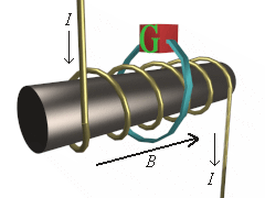
The illustration at right shows a solenoid encircled by a conducting loop of an arbitrary shape (click on the illustration to view a VRML model of the solenoid).
There is a current I that goes through the windings to set up a magnetic field B along the solenoid.
If a small galvanometer (G) is inserted in the loop and the current I is changed (and thus flux F would change), the galvanometer would indicate an EMF in the wire during the time that the flux is changing.
And this EMF corresponds to Faraday's law.
Before now, all the examples of induced EMF basically involved conductors moving in magnetic fields.
We introduced the idea of an induced EMF in stationary conductors with Faraday's Law.
Here is something new.
The illustration at right shows a solenoid encircled by a conducting loop of an arbitrary shape (click on the illustration to view a VRML model of the solenoid).
There is a current I that goes through the windings to set up a magnetic field B along the solenoid.
If a small galvanometer (G) is inserted in the loop and the current I is changed (and thus flux F would change), the galvanometer would indicate an EMF in the wire during the time that the flux is changing.
And this EMF corresponds to Faraday's law.If we take this one step further, we can equate the EMF to a line integral around the loop:
(Equation 6-81)
Let's say that the loop is a circle of radius r. So, the induced electric field at a distance r from the axis is:
(Equation 6-82)
Lenz's Law
This law is named after H.F.E. Lenz (1804-1864), a German scientist who duplicated many of Faraday and Henry's work without knowing their work. Lenz's Law states "the direction of an induced current is such as to oppose the cause producting it." The cuase of the current can be the motion of a conductor in a B field, or it can be the change in flux through stationary circuits like the examples we have just seen. The reason the current will oppose the B field is to presrve the law of conservation of energy. If it did not then you could get limitless energy just by moving conductors in B fields. With Lenz's Law we can state the completely correct state of Faraday's law:(Equation 6-83)
You can see that the only difference is the negative sign to introduce this opposition.