FizziCalc
Intermediate
Advanced
Cool Topics
Reference
Search
Games and Fun Stuff
Meeting Forum
Physics Links
Inductance |
|
Return to the Advanced Level Page.
In this section, we will begin to look at how an induced EMF affects current in a circuit.
Mutual Inductance
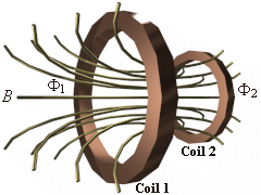
An EMF is induced in a stationary circuit whenever the magnetic flux through the circuit varies with time. If the variation is brought by a varying current in a second circuit, it is nice to express the induced EMF in terms of the varying current, instead of talking about varying flux. For our following examples, i represents the instantaneous value of a varying current. The illustration at right shows two closely wound coils of wire with a current i1 in coil 1 setting up a magnetic field, shown by the lines, some of which pas through coil 2.
The resulting flux through coil 2 is F2 and the B field is proportional to i1, so F2 is proportional to i1 as well.
So if i1 changes, F2 changes too, which induces an EMF in coil 2 given by:
The illustration at right shows two closely wound coils of wire with a current i1 in coil 1 setting up a magnetic field, shown by the lines, some of which pas through coil 2.
The resulting flux through coil 2 is F2 and the B field is proportional to i1, so F2 is proportional to i1 as well.
So if i1 changes, F2 changes too, which induces an EMF in coil 2 given by:(Equation 6-84)
The N2 is the number of coils in coil 2. It is used to take into account different scenarios in which coil 2 may be composed of several coils. Anyway, now we know that F2 and i1 are proportional to each other, we need a proportionality constant, which we will call M. So what you get is:
So basically we have:
![EMF[2] = M(di[1]/dt)](6-85.gif)
(Equation 6-85)
Hey, M, which stands for mutual inductance, depends only on the geometry of the two coils then. So, let's solve for M:
(Equation 6-86)
What if we varied the current in the second coil? Would the mutual inductance be the same in the first one? Yes, it would but would the proportionality constant M be the same? Seeing that the situation is not symmetrical you would not think that it would be the same had you flipped the situation around, but in fact it is. It is left to you to try to solve it the other way around.
Self Inductance
In the previous section, the circuit as the source of the B field was not linked to the circuit in which the EMF appeared. That meant that whenever a current in a circuit varies, it creates a B field around it as shown by Faraday's Law. And whenever a B field varies around a circuit, the current movement in the circuit will attempt to negate the B field as shown by Lenz's Law. So circuits with varying currents also have an induced EMF due to the B field it creates. This EMF is called a self-induced electromotive force.Let's talk about a circuit with N turns and a flux F pass through each turn. We define self-inductance L in the circuit just like we defined M for mutual inductance:

(Equation 6-87)
So if F and i change with time:

(Equation 6-88)
The self-inductance of a circuit is thus the self-induced EMF per unit rate of change of current. The direction of the field can be found with Lenz's law. If the current is increasing, the direction of the field is opposite to the current. The same applies if it is decreasing. Thus the change in current, not the current, that is opposed by the induced field.
The SI unit for self-inductance is the henry (H). The part of a circuit that has inductance is called an indcutor.
Energy in an Inductor
Because a charging current in an inductor causes an EMF, the source supplying the current must maintain a potential difference and so it must supply energy to the inductor. When an inductor carries an instantaneous current changing at a certain rate, the power supplied is:(Equation 6-89)
So the work would be:

(Equation 6-90)
R-L Series Circuit
 Since inductor has some resistance, and every resistor has some inductance.
So in order to distinguish the effects of the resistance R and the self-inductance L, the inductor will be resistance-less and the resistence will be inductor-less (this is a learning experience, but know that this never occurs in reality).
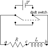
By means of a switch, the R-L circuit may be connected with a source of voltage V, or it can be shorted by the conductor across the lower terminals similar to the R-C circuit in a previous section.
This setup is shown in the circuit diagram at right.
Since inductor has some resistance, and every resistor has some inductance.
So in order to distinguish the effects of the resistance R and the self-inductance L, the inductor will be resistance-less and the resistence will be inductor-less (this is a learning experience, but know that this never occurs in reality).
By means of a switch, the R-L circuit may be connected with a source of voltage V, or it can be shorted by the conductor across the lower terminals similar to the R-C circuit in a previous section.
This setup is shown in the circuit diagram at right.Let's put the switch in the up position. Because of the self-induced EMF in the inductor, the current does not immediately jump to its final value. It grows at a rate that depends on the inductance and resistance of the circuit. Let i represent the current in the circuit at any time. The voltage across the inductor would be:
(Equation 6-91)
And the voltage across the resistor would be:
Therefore, the rate of increase of current for the entire circuit would be:

(Equation 6-92)
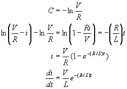
Well, let's start integrating:

(Equation 6-93)
Since we used an indefinite integral, we have a constant. We should get rid of the constant by plugging in some values for a scenario we know. Well, at time 0, isn't the current 0? So, let's plug them in and continue to get the final answer:

(Equation 6-94)
Now the time constant, or decay constant, is L/R, also commonly designated as just t.
Now it is time to flip the switch the other way and see what happens. We know the current will shut off, but since now the current decreases, the B field established will now oppose that decrease. You can use a similar derivation to get the equation of the decaying current, which is:
(Equation 6-95)