FizziCalc
Intermediate
Advanced
Cool Topics
Reference
Search
Games and Fun Stuff
Meeting Forum
Physics Links
Simple Circuits |
|
Return to the Intermediate Level Page.
When electric charge moves, this flow is called electric current. The rate at which charge passes through any given point in an electric circuit is called current (I). Current can be expressed as:
(Equation 2-5)
The unit for current is the ampere, which is the same as one coulomb of charge per second. A device used to measure current is an ammeter. In a circuit diagram, it has this symbol:
In order for current to flow, it must be in a closed path called a circuit. Also, in order to keep the charge flowing, there must be a potential difference between two points in the circuit. Potential difference (voltage) can be supplied by an electric cell or a battery (two or more cells connected). The symbols for an electric cell and a battery in a circuit diagram are:

The voltage in a circuit can be measured with a voltmeter, which has the symbol:
In the last section, we said that positive charges tend to move from points of higher potential to that of lower potential right? Well, that is the same with current flow. In a circuit, positive charge is said to flow from higher to lower potential. But wait a minute! Aren't electrons the charge carriers in moving charges? And electrons are negative! Yes, that is true. And you can blame this confusion on Benjamin Franklin (yes, the very same Ben Franklin you find in your American history book).
When Franklin first discovered electric current, he had no idea that electrons existed, nor did he know that electrons had negative charge. So, he decided to arbitrarily say that current is the flow of positive charge (don't you like to be more optimistic than pessimistic?). Well, even when the electron was discovered to be the charge carrier in a circuit, the world had already gotten used to Franklin's "conventional" current flow.
So, even today, the world still uses this standard of positive charge flow. It still works since the movement of positive charge can be considered the same as the movement of negative charge in the opposite direction. However, some physics textbooks and school curriculums are trying to reintroduce the movement of negative charge. In this section, we will stick to the conventional positive flow, so if you are learning negative flow at school, all you have to do is switch the direction to get the negative flow in most cases.
Resistance
Conductors are materials that permit the flow of charge through them. A good example of conductors are metals. Insulators are materials that resist the flow of charge. A good example of an insulator is rubber.Now, there are varying degrees at which materials will permit the flow of charge. This is called resistance. Most metals allow charge to flow freely and have low resistance. However some conductors may allow charge to flow, but will not let it flow as well as good metal conductors. These materials have high resistance.
Resistance (R) is defined as the ratio of the voltage applied to the ends of a material and the current that flows through it:
(Equation 2-6)
What does this mean? Well, if a material has high resistance, it will not let current pass as easily when a voltage is applied. If a material has low resistance, it will let current pass more easily. Wires in a circuit are usually considered having 0 resistance since they are very good conductors and have very little noticable resistance. The SI unit for resistance is the ohm (W). Also, equation 2-6 above is also called Ohm's law, which will be very useful later when we study some simple circuits.
For any type of material, the resistance varies with the length and cross-sectional area. For example, the longer a piece of wire, the larger the resistance, and the fatter a piece of wire, the smaller the resistance. A good metaphor for this is a water pipe. If the pipe was very long, there would be more resistance in getting the water through the pipe. However, if the pipe was wider and fatter, there would be less resistance in getting the water through. A mathematical expression for this relationship is:
(Equation 2-7)
L is the length, A is the cross-sectional area, and k is a constant that depends on the material and the temperature. Temperature also affects resistance too. In metals, resistance increases as temperature increases. However in nonmetals, resistance decreases as temperature increases.
A portion of a circuit that has resistance is called a resistor, which has the following symbol:
A Complete Circuit
Before we get into anything too complex, let's start out with the simplest circuit you can have. This circuit has an electric cell, a resistor, and a wires to connect them. This is a circuit diagram of such a circuit: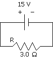
You can see that a wire comes out of the positive terminal (the longer line) of the electric cell and connects to a resistor, which connects back to the electric cell in the negative terminal (the short line). Positive charge flows from the positive terminal to the negative terminal (or if you're learning negative flow: negative charge flows from the negative terminal to the positive terminal). The electric cell has a voltage of 15 V. The resistor has a resistance of 3.0 W. What can we do with this?
Remember Ohm's law that was mentioned earlier? Well, the relationship is very useful in finding the current in the circuit. Ok, since there is only one resistor, the total resistance is still 3.0 W. If we want to find the current:
(Equation 2-8)
So we find that the current is 5.0 A.
Okay, we have all these numbers, but what do they mean? Well, let's go back to the water pipe metaphor. The wires in the circuits would be the pipes. The electric charge flow would be the water flow. The electric cell or battery would be the water pump. And the resistor would be something that slows the water flow down. Now, the voltage generated by the electric cell would be like the water pressure generated by the water pump. The current is how fast the water moves through the pipes. If there is a resistance in the way, the water would slow down (less current). If you increase the water pressure, the water would speed up (more current).
Series Circuits
If one or more resistors are connected end to end in a circuit, it is called a series circuit. Series circuits are not too hard to understand. Here is an example below:
Now, since it is one continuous loop, the current throughout the loop is the same. The total current is equal to the current in resistor 1 and resistor 2:
However the total voltage is spread across the loop. Using the same metaphor, each resistor decreases the water pressure after the water passes, so:
And because of the same reasons, the total resistance is the sum of the resistances in each resistor:
Parallel Circuits
In a parallel circuit, the resistors are hooked up side by side instead of end to end. Below is an example of a parallel circuit: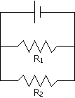
Parallel circuits operate a little differently from series circuits. First of all, the current that goes through the two resistors can be different. This is because, if we use the water metaphor again, the water is split between the two possible paths. So, the total current is just the sum of the two currents in the resistors:
Also, the voltage across both of the resistors are the same. If we use the metaphor, the water pressure applied by the pump is the same on the ends of the resistors facing the positive terminal (or the negative terminal for negative flow).
To find the total resistance from each of the individual resistors, we have to use Ohm's law to substitute into the previous equations:

(Equation 2-9)
Combination Circuits
Let's put everything we just learned into another all encompassing example. Find the total resistance and current, then find the individual voltages and currents for each of the resistors in this circuit: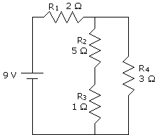
Does the circuit above look intimidating? Well, it is really not that bad if you take it one step at a time. Usually in circuits, you work from the inside out. Just take parts of the circuit that are doable and keep doing it until you simplified it completely.
Okay, now let's look at our circuit. Aren't resistor 2 and resistor 3 in series? Let's call this part of the circuit A. Since they are in series, the resistance of part A of the circuit is just the total resistance of resistors 2 and 3:
So, we can treat part A just like it was one resistor with a resistance of 6 W. Okay, now we simplied the circuit to this:
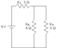
In this circuit, we see that resistor A and resistor 4 are in parallel. We'll call this part B. To find the total resistance of part B, we'll use the equation for a parallel circuit:
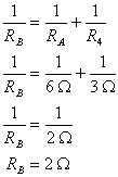
(Equation 2-10)
By the way, look at what the total resistance for part B is compared to the resistances that comprise it. The total resistance is much lower. That means that more current will flow through a parallel circuit. If we use the pipe metaphor again, it is like two pipes side by side that allow water to flow through both of them more easily. However, this is also one reason why you never should plug too many things into the same outlet. Too much current can damage or even burn a wire.
Anyway, now that we have part B, the circuit is simplified to this:
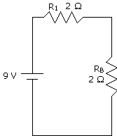
This is pretty easy now. It's just a series circuit. So now we can find the total resistance:
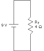
Okay, now that we have the total resistance, we can get the total current:
(Equation 2-11)
Okay, to get the currents and voltages through each of the resistors, we have to work backwards now. We know the total current is 2.25 A. Let's look back at this circuit:

In a series circuit, the current through each resistor is the same as the total. So, I1 = 2.25 A and IB = 2.25 A. Therefore:
and
VB = IBRB = (2.25 A)(2 W) = 4.5 V
Now that we know the current and voltage in B, we can look at the next part of the circuit:

Now, part B of the circuit is a parallel circuit, and in a parallel circuit, the voltages are equal. So, VA = 4.5 V and V4 = 4.5 V. Therefore:
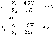
(Equation 2-12)
We have part A so we can finish up the circuit.

Part A is a series circuit, so the current is the same. So, I2 = 0.75 A and I3 = 0.75 A. Now we can find the voltages of the remaining resistors:
and
V3 = I3R3 = (0.75 A)(1 W) = 0.75 V
And we are done! Let's organize everything so we can see our results better:
| Resistor | Resistance (W) | Voltage (V) | Current (A) |
|---|---|---|---|
| Total | 4 | 9 | 2.25 |
| 1 | 2 | 4.5 | 0.75 |
| 2 | 5 | 3.75 | 1.75 |
| 3 | 1 | 0.75 | 0.75 |
| 4 | 3 | 4.5 | 1.5 |